Last reviewed and updated: 10 August 2020
Windows 8 quietly saw the introduction of many new Windows OS-level features. One of the most notable was support for devices connected via a Simple Peripheral Bus (SPB). SPBs are low-cost, low-power, low-speed buses that are most often used for connecting relatively simple peripherals such as sensors. Examples of SPB devices supported in Windows include I2C and SPI. Prior to Windows 8, these types of buses were restricted to use by the BIOS. But starting in Windows 8, support for these devices went mainstream.
There are several things that are interesting about SPB buses and about writing a driver for a device that’s connected via an SPB bus. This article explores some of these topics.
SPB Buses – Topology and Enumeration
Like the SCSI, SATA, and USB buses, SPBs are protocol-based buses. That means there’s a Controller that’s responsible for getting requests on and off the bus using the appropriate protocol and according to the bus’s specific rules. Devices that connect to protocol-based buses are called Client Devices (See Figure 1).
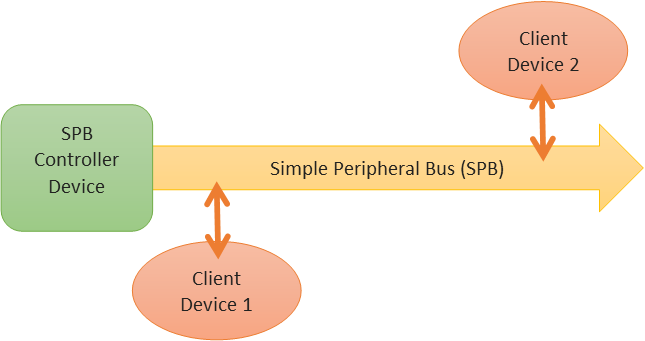
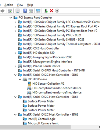
One point about these buses that causes some confusion is the way devices on an SPB bus are discovered and enumerated. SPB buses are not dynamically enumerable. That means that there’s no way to discover which Client Devices, if any, are connected to a given SPB bus at run time. So, how do Client Devices on an SPB bus get discovered as part of the Windows PnP process? The answer is simple: The description of which Client Devices are attached to which specific SPB bus is supplied statically, in a table, as part of the ACPI BIOS. As a result, the Bus Driver that enumerates SPB Client Devices is ACPI, and not the SPB Controller Driver. Because the SPB Controller Driver is a standard backplane-bus type device it’s enumerated by the PCI bus driver. You can see these points in Figures 2 and 3.
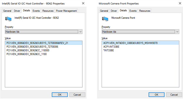
The ACPI table that contains this description is called the Differentiated System Descriptor Table or DSDT for short. The DSDT is usually provided in ROM and supplied by the system integrator, typically the OEM who builds the computer system. This works well because SPB Client Devices are usually permanently integrated into a system platform; That is, they’re almost always soldered directly onto the system’s main board. In the rare case that an SPB Client Device can be dynamically attached to a system (such as a specialized detachable keyboard that’s connected via an I2C bus), the information about the Client Device is still provided to the ACPI BIOS and the device will be enumerated by ACPI.
Common Uses
Windows supports both the SPI bus and the I2C bus using the SPB model. The I2C bus uses only 2 wires (plus power) for communication, making it an extremely simple interface. The SPI bus uses 4 wires (plus power). While initially these buses were primarily of interest to very small systems, such as smart phones and tablets, they have become very popular for interfacing “simple” devices on a wide variety of systems. In fact, Windows now includes I2C as a standard method for connecting HID devices, and it is very popular among touchpad vendors. The Surface Pro 4 has more than a half dozen devices, ranging from cameras to power meters to a variety of HID devices that interface via the I2C bus. You can see some of these devices in Figure 2 (which was captured on a Surface Pro 4).
Writing SPB Drivers
As you can probably guess, there are two very different types of drivers that one could possibly write for SPB devices. There are drivers for the SPB Controller Device and drivers for SPB Client Devices.
Drivers for both types of SPB devices have special support in WDF that’s provided by the SPB Class Extensions (SPBCx). SPBCx provides a standardized infrastructure that makes writing drivers for both categories of SPB devices much less difficult than it would be otherwise. Among other things, the SPBCx defines a set of I/O requests that a driver for a Client Device can send to the driver for a Controller Device to access their device. These standard I/O requests include specific rules for how read and write operations are processed by the driver for the Controller Device, as well as a standardized set of SPB-specific IOCTLs.
Aside from supporting the SPBCx, writing a driver for an SPB Controller Device is mostly like writing any driver for a device on a backplane architecture bus like PCI or PCIe. These drivers claim their hardware resources (such as registers, perhaps a DMA channel, and one or more interrupts) as part of their EvtDevicePrepareHardware Event Processing Callbacks. In most respects, an SPB Controller driver is a pretty ordinary Windows driver. Because the driver for SPB Controller Devices are almost always written by the OEM/IHV and supplied as part of a system, there aren’t many of these drivers written. As a result of all these factors, we won’t discuss writing divers for SPB Controller Devices further in this article.
Drivers for SPB Client Devices resemble those for any device that’s accessed via a protocol-based bus. An SPB Client Device driver opens a Remote I/O Target to its Controller Device, and interacts with its device by formatting WDFREQUESTs and sending them to the Controller Device.
In terms of hardware resources, a Client Device driver will always receive a “Connection ID” in the EvtDevice PrepareHardware Event Processing Callback. It might also receive one or more GPIO resources, which can be used to provide out of band data or interrupts from the Client Device to the driver.
The Connection ID is an opaque identifier that the Client Device driver uses to open a Remote I/O Target to the specific SPB Controller Device to which the Client Device is attached. The process of opening the Remote I/O Target to the correct Controller Device is accomplished with the assistance of another system component called the Resource Hub.
The code that a driver for a Client Device uses in its EvtDevicePrepare Hardware Event Processing Callback to create and open a Remote I/O Target given a Connection ID is shown in Figure 4.
                       case CmResourceTypeConnection: {

                WDF_IO_TARGET_OPEN_PARAMS  openParams;
                WDF_OBJECT_ATTRIBUTES targetAttributes;
                WDF_OBJECT_ATTRIBUTES_INIT(&targetAttributes);
                DECLARE_UNICODE_STRING_SIZE(resHubPath, RESOURCE_HUB_PATH_SIZE);

                //
                // Create the device path using the connection ID.
                //
                status = WdfIoTargetCreate(devContext->WdfDevice,
                                           &targetAttributes,
                                           &devContext->SpbControllerTarget);

                if (!NT_SUCCESS(status)) {

                    // ...

                }

                //
                // Using the Connection ID, create the NAME pointing to the
                // Resource Hub.  The Resource Hub will resolve this open
                // by redirecting it to the appropriate Controller Driver
                // (the one to which our device is attached)
                //
                RESOURCE_HUB_CREATE_PATH_FROM_ID(&resHubPath,
                    resourceTrans->u.Connection.IdLowPart,
                    resourceTrans->u.Connection.IdHighPart);


                //
                // Open a Remote I/O Target to the SPB controller
                //
                WDF_IO_TARGET_OPEN_PARAMS_INIT_OPEN_BY_NAME(&openParams,
                                                            &resHubPath,
                                                            (GENERIC_READ | GENERIC_WRITE));

                status = WdfIoTargetOpen(devContext->SpbControllerTarget,
                                         &openParams);

                if (!NT_SUCCESS(status)) {

                    // ...
                }


                status = Bme280InitializeDevice(devContext);
                status = STATUS_SUCCESS;

                break;
            }
In Figure 4, on receiving a Connection ID hardware resource you can see that the Client Device driver first creates an empty I/O Target object by calling WdfIoTargetCreate. Assuming the empty I/O Target is created successfully, the driver next builds a Resource Hub name with the macro RESOURCE_HUB_CREATE_PATH_FROM_ID passing in the received Connection ID (passed in the translated resources in u.Connection.IdLowPart and u.Connection.IdHighPart). This name is used during the I/O Target open process to identify the Client Device to the Resource Hub when the I/O Target is opened. Finally, the driver calls WdfIoTargetOpen to open the Remote I/O Target.
More About Connecting SPB Client Devices to Controller Devices
Opening that Remote I/O Target to the Controller Device involves some pretty cool magic. The Connection ID that’s built into the Remote I/O Target name uniquely identifies the Client Device to the Resource Hub. The Resource Hub, on receiving the open, checks the Client Device resources from ACPI and re-routes the I/O Target open operation to the correct Controller Device (Figure 5). This alleviates the Client Device driver from having to figure out which SPB controller instance its Client Device is connected to (and it is very common to have multiple SPB controllers in a system). In addition, when the Controller Device driver receives the open for the Remote I/O Target, it knows to which specific Client Device the open corresponds (via information from SPBCx). This allows the Controller Device driver to determine the bus address to use to communicate with the Client Device. Because the Controller Device driver has this information, the Client Device driver never needs to know (and in fact, generally cannot know) the address of its device on the bus. The bus address is completely handled by the Controller Device driver.
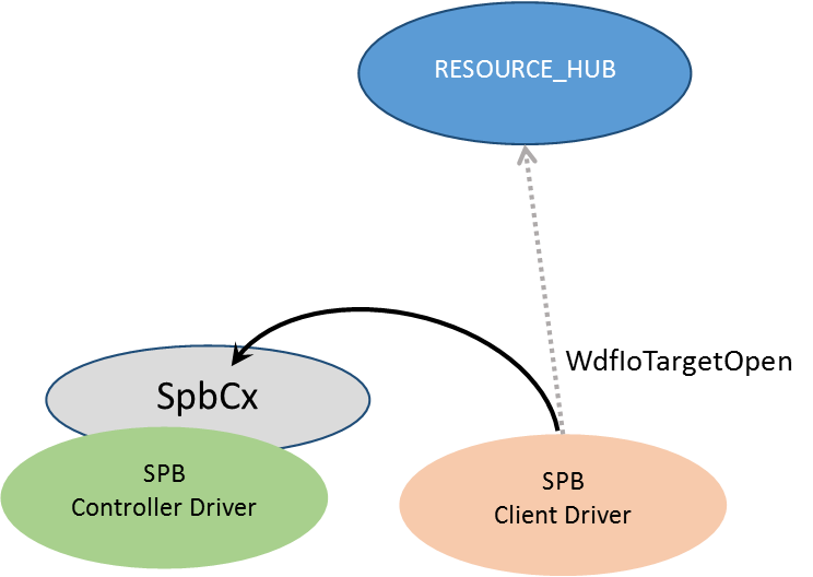
But there’s another benefit to this Resource Hub and SPBCx integration mechanism. Because SPBCx provides a uniform interface for Client Device drivers to use to interact with the Controller Device driver regardless of whether the Client Device is connected via I2C or SPI, making the connection via the Resource Hub and SPBCx also eliminates the Client Device driver from having to know the type of bus to which the Client Device is physically connected. Thus, if you’re writing a driver for an IHV that makes a given sensor device, for example, and if that device can be connected via either I2C or SPI (which is quite common), your driver doesn’t have to change at all based on how the device is physically connected. How cool is that?
Reading and Writing Client Data
Once the Remote I/O Target is opened to the Controller Device, the driver for a Client Device can perform READ and WRITE operations on its device via the Controller Driver using WdfRequestSend to send ordinary read and write Requests. However, this isn’t typical of how a driver interacts with an SPB Client Device. This is because the typical sequence of operations that the Client Device driver uses to read data from an SPB Client Device usually involves at least two operations. The most common pattern is:
- The Client Device driver sends a write to the Remote I/O Target representing the Controller Device. This write is typically one byte in length and comprises a value indicating which register on the Client Device it wants to read;
- The Client Device driver sends a read to the Controller Device’s Remote I/O Target to read the data from the previously specified register. The number of bytes to be read is device specific and depends on the data that’s being retrieved.
Pretty simple, right? The only trick that’s involved is that the write and the read must generally take place in adjacent transactions on the SPB bus. That is, the Controller Device driver can’t process the WRITE to the Client Device (to select the appropriate device register), then process a read or write to some other device on that same SPB bus, and then process the READ for the Client Device. That just won’t work.
Again, SPBCx significantly simplifies things for the Client Device driver writer by providing an IOCTL design to perform the sequence described above. That IOCTL is IOCTL_SPB_EXECUTE_SEQUENCE. This IOCTL takes an SPB_TRANSFER_LIST in its Input Buffer. An SPB_TRANSFER_LIST contains a header and one or more SPB_TRANSFER_LIST_ENTRIES. Each TRANSFER_LIST_ENTRY contains a description of the direction of the transfer (that is, if the requested transfer is a write operation to the device or a read operation from the device), and a description of the data buffer to be used. The data buffer description can either be provided by a kernel virtual address and length in bytes, or an MDL. The number of SPB_TRANSFER_LIST_ENTRIES provided is indicated in the SPB_TRANSFER_LIST_HEADER. Figure 6 illustrates an SPB_TRANSFER_LIST.
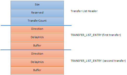
In Figure 6, you can see an SPB_TRANFER_LIST that describes a sequence of two transfers. The header for the Transfer List is shown in blue. Each transfer is described by a Transfer List Entry.
For example, to read four bytes starting at a specific register address on the Client Device, the driver would set the TransferCount field to 2, indicating that two TRANSFER_LIST_ENTRY structures would be used to represent the overall operation. It would set the first TRANSFER_ LIST_ENTRY to represent the write of the register number to the Client Device. The Client Device driver would set the Direction field of the first TRANFER_LIST_ENTRY to SpbTransferDirection ToDevice, indicating a write operation to the device. The driver would put the Client Device register number from which it wanted to read into a buffer, and set the Buffer field of the first transfer list entry to point to that buffer, indicating a length of one byte. The second TRANSFER_LIST_ENTRY would then be set up to represent the read operation. The Direction in the second TRANSFER_LIST_ENTRY would be set to SpbTransferDirectionFromDevice, and the Buffer field of this TRANSFER_LIST_ENTRY would be set to point to a data buffer to hold the 4 data bytes read from the device.
You might also notice the DelayInUs field in each TRANFER_LIST_ENTRY. This field allows the driver to specify a minimum amount of time that should take place before a given transfer is initiated. One use for this delay is to allow a Client Device time to perform a specific operation that’s been requested by one transfer in the sequence before, for example, starting a read for the results of that operation by a subsequent transfer in the sequence.
An example of a generic routine that will read a specified number of bytes from a given SPB device register is shown in the OSRSpbReadRegisters function in Figure 7.
_Use_decl_annotations_
NTSTATUS
OSRSpbReadRegisters(PBME280_DEVICE_CONTEXT DevContext,
                    UCHAR StartingRegister,
                    PVOID OutputBuffer,
                    ULONG OutLength)
{
    NTSTATUS status;
    WDF_MEMORY_DESCRIPTOR sequenceBufferDescriptor;
    ULONG_PTR bytesTransfered;

    //
    // Allocate space for a 2 entry transfer list
    // for the Sequence of operations: WRITE followed by READ
    //
    SPB_TRANSFER_LIST_AND_ENTRIES(2)    tList;

    //
    // Initialize the list
    //
    SPB_TRANSFER_LIST_INIT(&tList.List, 2);

    //
    // Initialize the WRITE with the register number that we want to fetch
    // (this is just one byte)
    //
    tList.List.Transfers[0] = SPB_TRANSFER_LIST_ENTRY_INIT_SIMPLE(
        SpbTransferDirectionToDevice,
        0,                          // No delay
        &StartingRegister,
        sizeof(StartingRegister));

    //
    // And initialize the READ with the place to store the returned value
    //
    tList.List.Transfers[1] = SPB_TRANSFER_LIST_ENTRY_INIT_SIMPLE(
        SpbTransferDirectionFromDevice,
        0,                     // No delay
        OutputBuffer,
        OutLength);

    //
    // The send operation wants the buffer described with a MEMORY_DESCRIPTOR,
    // so that’s what we build here.
    //
    WDF_MEMORY_DESCRIPTOR_INIT_BUFFER(&sequenceBufferDescriptor,
                                      &tList,
                                      sizeof(tList));

    //
    // Send the sequence to the device: a 1 byte WRITE, followed by READ of the
    // amount of data specified.
    //
    status = WdfIoTargetSendIoctlSynchronously(DevContext->SpbControllerTarget,
                                               NULL,
                                               IOCTL_SPB_EXECUTE_SEQUENCE,
                                               &sequenceBufferDescriptor,
                                               NULL,
                                               NULL,
                                               &bytesTransfered);

    if (bytesTransfered != OutLength + 1) {

#if DBG
        DbgPrint("Bytes Transfered... expected 0x%0x, got 0x%0x",
                                                      (OutLength + 1),
                                                       bytesTransfered);
#endif
        status = STATUS_BAD_VALIDATION_CLASS;
    }

    return(status);
}
In the example shown in Figure 7, the routine uses the macro SPB_TRANFER_LIST_AND_ENTRIES to allocate an SPB_TRANSFER_LIST with two SPB_TRANSFER_LIST_ENTRY structures. The Transfer List Header is then initialized using the SPB_TRANSFER _LIST_INIT function. The routine then initializes the two SPB_TRANSFER_LIST _ENTRY structures to describe each transfer: The first entry describes a one-byte write that contains the register number from which the read is to be performed. The second entry describes a read. Note that the routine uses the SPB_TRANFER_LIST_ENTRY_INIT_ SIMPLE macro to initialize each of these SPB_TRANFSFER_LIST_ENTRY structures, and describes the data buffer using a kernel virtual address and buffer length in bytes. The routine then builds a MEMORY_DESCRIPTOR to describe the buffer containing the SPB_TRANSFER_ LIST (because that’s what the Send function that it uses wants). It then calls WdfIoTargetSendIoctlSynchronously to send the sequence to the Remote I/O Target that represents the Controller Device. Note that because it sends the sequence to the Remote I/O Target synchronously, this routine must be called at IRQL PASSIVE_LEVEL.
It’s That Easy
With no complex configuration and the assistance provided by the SPBCx and the Resource Hub, writing a driver for an SPB device can be quite easy. As should be the case in WDF drivers, the Framework and the available Class Extensions work together to make much of the interfacing details simple (see sidebar, What Are WDF Class Extensions? below). This frees you up and allows you to spend your time determining how best to interact with your device and get your project done. That’s not to say that everything about these devices is always simple, of course. For example, power management for SPB devices can sometimes be complex when these devices are integrated into system that support Modern Standby. But that’s a topic for a whole other article.
In our WDF Core Concepts seminar, we spend time talking about the new buses that Windows supports, including SPB but also GPIO and async. If you’d like to learn more about writing drivers for these types of devices, we hope you’ll join us.
[infopane color=”6″ icon=”0182.png”]What Are WDF Class Extensions?
Starting in Windows 8, the concept of WDF Class Extensions was introduced. Class Extensions provide a way to add support for a new class of device, such as SPB devices or NFC devices, into WDF without having to modify the underlying Framework itself. Class Extensions differ from other extended WDF support for (such as, for example, that provided for USB devices) because instead of the device class support being part of the Framework, it’s supplied by an added DLL. This DLL, plus the Framework, plus the driver together form a complete entity.
Aside from the fact that they do not physically form part of the WDF Framework, what most quickly identifies a function as belonging to a Class Extension as opposed to the core WDF Framework is its name. The names of functions implemented by and structures defined by a Class Extension begin with an extension-specific prefix. For example, the functions provided by the SPB Class Extensions start with “Spb” (such as SpbRequestComplete, which are used by drivers for SPB Controller Devices, or the previously discussed SPB_TRANSFER_LIST structure). As a second example, functions provided by the NFC Class Extensions all start with “NfcCx” (such as the NfcCxDeviceInitialize function or the NFC_CX_SEQUENCE structure).
Other than the naming conventions and the fact that they do not physically form part of the WDF Framework, Class Extensions are pretty much indistinguishable from any other type of WDF support. Class Extensions can define unique Event Processing Callbacks that a driver can implement. They can also perform processing of standard WDF callbacks either in place of, or in addition to, those provided by a WDF driver.
[/infopane]
